Robot |
<Snar_2> an improved automated snare drum made to the order of Aphex Twin Godfried-Willem RAES 2014 |
This musical robot consists of a high quality Ludwig snare drum automated with
13 beaters hitting different spots of the membrane from the inside. Two solenoid
driven drum sticks, mounted externally, take care of the rimshots. Of course,
all beaters have a precise and wide range velocity control. The snares can be
activated through a special dual solenoid driven mechanism, offering gradual
control as well as some special effects. Controlling this robot is realized
using a standard midi protocol. It was designed following the model of our <Snar>
robot as a commission from Aphex Twin, who also delivered us the snare drum
to be automated. One of the elements that forced us to recalculate and redraw
the design was in the fact that this snaredrum has ten tuning pegs whereas <Snar>
only had eight. Also, this snare drum is equipped with an internal controllable
damping felt pad, occupying some space. Although possible, we decided not to
automate this component. All these differences made placement of automation
components in this snare drum a bit more complicated. This is a picture of the
drum before any modifications, except taking the beater skin off to get access
to the inside:
From an electronics point of view, there were no new problems to be solved in the development of this automate, except to a certain extend the snare push and release mechanism, involving gradual control using PWM on two separate solenoids.. The mechanics for the rimshot beaters are an improvement over the first design. Here we use heavy duty pull-type solenoids.
The height of the final robot is determined by the height of the drum itself, the height of the electronic components -in particular the hefty power supply- and the acoustical requirement that for preservation of the sound integrity of the drum a free space of about half the skin diameter had to be reserved between the resonance skin underneath and the electronic components on the base. For mechanical reasons, the drum should only be used in a fully horizontal position.
Power supply voltages and currents:
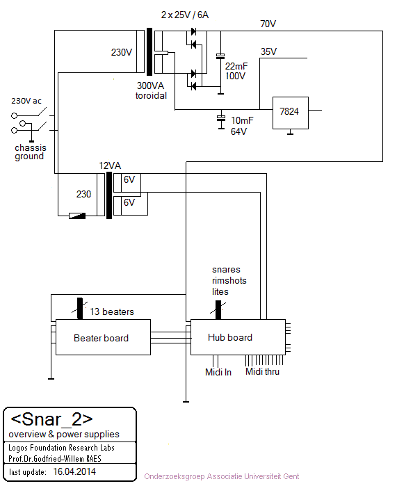
- 35 V / 70 V/ 6 A linear power supply for solenoids and electronics (300 VA)
- 5 V / 500 mA for the midi-input and PIC processor boards
Midi Mapping and implementation:
- Midi channel: 9 (counting 0-15)
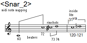
- Midi note range: 60 - 74. Notes 60-72 regular skin beaters, 73-74 rim shots. The lights are mapped on notes 120 and 121. For these the velocity byte steers the flashing speed. When the velocity byte for the lights is 127, they stay on without flashing. Switching the lights off can be achieved either by sending a note off command or a note on command with velocity set to zero.
- Note Off commands are not required for the beaters. They are required for the lights. Velocity is implemented and has a wide control range.
- Controllers:
- Midi controller 9: snare pressure for solenoid 1:. 0= snares loose, 127= snares on with maximum pressure. For continuous ON, do not exceed 90.
- Midi controller 10: snare pressure solenoid 2: 0= snares loose, 127= snares on with maximum pressure.For continuous ON, do not exceed 90.
- Midi controller 11: control's both solenoids together: 0= snares off, 127=
snares on with maximum pressure.For continuous ON, do not exceed 90.
- Note with regard to controllers 9,10 and 11: If values higher than 90 are send, the firmware will start a timer such that after a while, proportional to the requested overpressure, the force will fall back to the value corresponding with 90. This to stay within the limits of the maximum allowable duty cycle for the solenoids.
- Note with regard to controllers 9 and 10: if these are send in an alternating sequence, the snares will cause a shuffling sound as they slide over and back against the resonant drumskin.
- Midi controller 14: can be used to set the minimum velocity value to make the beaters inside the drum hit. The default startup value is 14.
- Midi controller 15: can be used to set the minimum velocity value required for the rimshot sticks. The default startup value is... [to be determined]
- Midi controller 16: can be used to set the minimum value required to activate the snare solenoids. The default startup value is 48.
- Midi controller 66: Power up/down controller. Power down causes all notes off and resets all controllers to the default startup values. Parameter value 0 causes power down, any other value causes power up.
- Midi controller 123: all notes off, releases the snares and switches off the lights. It does not reset controllers 14 , 15 and 16.
![]()
Technical specifications:
- size: 640 mm height, circular, diameter: 485 mm (the rimshot sticks, stick out 200 mm)[ flightcase sizes: height: 680 mm, width: 725 mm, depth: 573 mm]
- weight: 22 kg [case: 31 kg], drum with case: 53 kg.
- power: 230 V ac / 300 W (max.) [the instrument is not fused, the UK-type power chord having a fuse]
- control: Midi IN, 5 x midi thru.
- Insurance value: 6.800 Euro
Design and construction:dr.Godfried-Willem Raes
Collaborators on the construction of this robot:
- Kristof Lauwers
- Mattias Parent
Construction Diary:
- 20.03.2014: The Ludwig snaredrum was delivered at Logos from Aphex Twin.
- 21.03.2014: research into suitable solenoids.
- 22.03.2014: Close examination of the existing and working <Snar> robot to figure out possible improvements.
- 23-24.03.2014: Sketches of the mechanics
- 25-26.03.2014: experiments with alternative rimshot mechanisms.
- 27.03.2014: Decided to use Black Knight tubular solenoids for the beaters inside the drum. In this design we will not place the microprocessor board inside the drum as we did for <Snar>. Black Knight, type 121-420-620-620, 12 V dc @ 100%. DC resistance: 20 Ohm. Mounting thread: 18UNF - 0.562" (13,8 mm).
- 28.03.2014: Stainless steel profiles selected. Clamping mechanism for the drum worked out such that it can easily be removed.
- 29.03.2014: Drawing and recalculation of the electronic circuitry. Each solenoid on the beaters draws 600 mA at 12 V, so for all beaters together we need 7.8 A of current. However, we work at 60 V with a duty cycle not larger than 5%, so calculation becomes 3 A * 5% * 13 = 1.95 A average with all beaters playing. Peak current can be quite a bit higher at times. We can use a non stabilized power supply, functioning as a kind of build-in compressor.
- 30.03.2014: Toroidal transformers ordered from Farnell for the solenoid power supply. We plan the use a purely analog linear supply as it behaves more robustly under fast switching inductive loads conditions.
- 31.03.2014: Extra 28 output pulse boards ordered from Eurocircuits. Technical drawings for a possible welding plan. The drum has ten tuning screws, thus we will have to perform some triangulation to find out the perfect shape for the stand, the angles for the placement of the rimshot beaters etc... We do prefer a triangular base with three wheels in this design.
- 01.04.2014: Start cutting, drilling and welding works on the beaters assembly.
This is made with to lengths of 30 x 30 x 3 L-profile, 332 mm. These are TIG-welded
together to form a [ profile, height 60 mm. The thirteen holes for the solenoids
are drilled and honed to 14.5 mm diameter. All metal works will be made of
stainless steel.
On the sides we provide two pieces of 60 x 10 flat stainless steel with M10 threaded holes for mounting the assembly inside the drum.
- 02.04.2014: Detailed technical drawing finished, scale 1:1. The original
drawing is size A2.
- 02.04.2014: Removal of the existing mechanism for the snares:
Solenoids to be used for the snares: ZMF-3864Z.001-24 V DC, ordered from Conrad. Order nr. 542-162-17. We will use one solenoid on each side of the snares, thus doubling the force as compared to <Snar>. This is what these look like before further preparation and modifications:
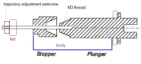
The solenoids can be mount on the drumshell directly with four M4 bolts and nuts. A fall-down stop with a felt pad had to be added to the anchor. This was made on the lathe after this drawing:.
![]() The M3 thread inside the plunger was done by hand. The threaded M3 shaft is
turned into the M3 internal thread in the plunger with Loctite fastener. Both
snare solenoids mounted on the drum using M4 x 10 bolts and two growers as
standoffs.
The M3 thread inside the plunger was done by hand. The threaded M3 shaft is
turned into the M3 internal thread in the plunger with Loctite fastener. Both
snare solenoids mounted on the drum using M4 x 10 bolts and two growers as
standoffs.As the DC resistance of these solenoids is 34 Ohms, the current drawn at 24 V is 705 mA. If we use an unregulated power supply, the output voltage would be 35.35 V using a 25 V ac transformer. The peak current becomes than 1 A for each solenoid. Thus this part of the power supply needs to be rated for 2 A / 35 V = 70 VA minimum. We could also connect both coils in series, but in that case we loose the possibility for separate control over the snare sides. It might be an idea to fit overtemperature protectors on these solenoids, as they can get very hot.
- 03.04.2014: Alignment of the snares mechanism. Solenoids for the rimshots
ordered from Conrad as we didn't have any in stock. These solenoids will mount
on the drumshell as well. Welding work on the beater assembly. Mounting of
the Bakelite beaters, placement of the beater solenoids in the beater assembly.
Mounting holes drilled and threaded with M10. Fallback felt pads glued under
the beater anchors. The thickness of these pads regulates the maximum beater
trajectory. First adjustment of the beaters:
. View on the inside of the drum with the mechanism mounted:
Between the beater assembly and the inside of the drum shell, we fitted a layer of vibration dampening hard rubber. The mounting holes for the assembly in the drum have been filed out to allow for a few millimeters of adjustment for the beaters. The beaters ought to be adjusted such that when active, they just hit the drumskin. If for any reason, the user thinks the trajectory (in our design 5 mm) is too small, it can be enlarged by replacing the fallback felts with single layer felt. (We used 2 layers). However, enlarging the traject reduces the repetition speed and reduces the velocity sensitivity to a great extend.
- 04.04.2014: Start working on the PC boards: component placement and selection. Decided to use a 14-output pulse hold board for the beaters. No need to mount the components for the negative pulse. Firmware has to use the hold outputs as pulse outputs. The decision to use this board instead of the 28 output pulse board was taken because the space this board occupies is much smaller. So <Snar_2> will use the midi hub board in combination with the 14 output board.
- 06.04.2014: The hunt for small wheels with brakes was successful today, so the construction of the chassis can go on.
- 07.04.2014: Start practical construction of the rimshot stick holder with
spring and pivot. Here is a picture of the construction drawing:
Materials and sizes used: 20 x 10 x 50 (2 pieces) , 30 x 3 x 180 (4 pieces, cut under 60 degrees). The rimshot solenoids came flowing in today: Tremba type ZMF-3258z.001. Precision is in order here, as a fraction of a millimeter fault makes real rimshots impossible to perform. The drumstick has to touch the skin and the rim at the same time.
Sizing also seems to be pretty dependent on the kind of drumstick used. This design is based on standard snare drumstick with a diameter not larger than 14 mm. The length of the sticks is ca. 40 cm. The decision as to use either weight for stick fall back or a spring is open as yet. Springs have an inherent problem with resonance's, whereas weight may make operation sluggish. The picture shows the experimental set up, using counterweights.
- 08.04.2014: A full working day spend on the rimshot mechanism. Here are
some pictures:
In this picture we used temporary weights to let the sticks go high again after each stroke. This seems to work better than using springs. Of course in the definitive version we will mount new stainless steel rings, retaining the possibility of place adjustment of the weight. The mechanical connection between the anchor of the solenoid and the drumstick was realized with a piece of PVC covered twisted steel wire. The clamping mechanism above the stick allows for easy adjustment. The holes drilled through the drumstick are 3 mm in diameter.
Note that the solenoids are mounted on the shell of the drum using four rubber mount bobbins with male M4 threads. (Ordered from Farnell). This guarantees that noise from the solenoid will not be transferred to the drumskin.
An extra advantage is that we cannot cause deformation of the drumshell by overtensioning the nuts. We already tested the construction under electric excitation of the solenoids and indeed, this mechanism performs better than what we did on <Snar>. Note that it is still possible to remove (and replace) the beater side skin without disassembling any of our added mechanical parts.
- 09.04.2014: Start construction of the chassis parts for the power supplies. The three vertical poles are square stainless steel profile 25 x 25 x 565, thickness 2 mm. The toroidal transformer (300 VA) mounts vertically against a bend stainless steel plate, thickness 2 mm, that also holds the power inlet and the on/off switch. All mounting holes for the electronics and power supply components measured out and drilled. Heat sinks will be required on the solenoid driving MOSFETS for the snare mechanism.
- 10.04.2014: Construction of the wheel base. Welding works.
- 11.04.2014: Saving some welding work for the TV shootings today... Always good for some nice shots.
- 12.04.2014: Designing a clamping mechanism for the drum on the stand. Three small wheels with brakes mounted using M8 countersunk bolts.
- 13.04.2014: Wiring and testing of the power supplies.
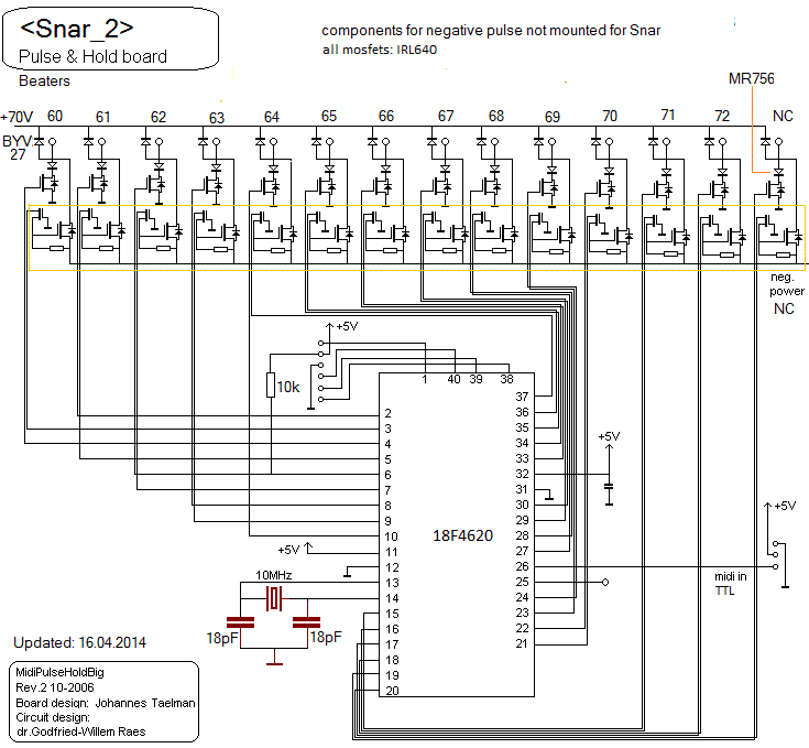
- 15.04.2014: Soldering of the microprocessor board for the beaters. (PIC 18F4620 processor). Wired for 14 pulse outputs. The MOSFET's are all IRL640. We are running out of fast recovery diodes, so quickly ordered some MURD620's and MR756 from Farnell... Anyhow, we can already start the coding for the PIC processor. Source code can be found here.
- 16.04.2014: Board for the beaters finished and tested. MR756 diodes used. The board can be mounted on the chassis plate now.
- 17.04.2014: Soldering of the 18F2525 board.
- 18.04.2014: Finishing the 18F2525 board, start writing the firmware. Construction of the counterbalancing weights in red copper for the rimshot sticks on the lathe. These weights have an M6 set screw for adjustment.
- 19.04.2014: Wiring of the beater assembly and all components placed inside
the drum. Two white LED strips are mounted near the rim inside the drum. These
are to be controlled by the processor on the hub board. They require a 24V
supply voltage. Hence we mounted a TO220 7824 voltage regulator straight on
the chassis. PG16 cable gland entry made on the drum: 25 mm hole punched out.
Wiring of all connectors to the board. Spirawrap applied where needed. Electrically, <Snar_2> is nearly fished now.
Electrical test: we left Snar2 turned on for over 24 hours without any problem.
- 20.04.2014: Test code written in GMT. Testing of version 1.0 of the firmware. Measurement of the behavior. First adjustment of the beater assembly. On the first try - with the beaters against a piece of metal- the Bakelite balls broke. The velocity scaling is too high and may be even high enough to punch holes in the drumskin... Adjustment of the snare mechanism and the rimshots. Everything in principle seems to work just fine. Nevertheless, there is still a lot of fine tuning to be done, both in the firmware and in the mechanics. Test: we let Snar2 run through the night with the software running. No apparent problems encountered.
- 21.04.2014: Teflon (PTFE) slider constructed for smooth and frictionless
operation of the snare lifter.
New and definitive large M3 brass setscrews (with felt pad) for adjustment of the snares, turned on the lathe.
Fine tuning of the mechanics. Clamping mechanism to hold the drum in place designed and welded.
The picture shows the test assembly using clamps, before welding together the parts. The assembly is made from a piece of rectangular stainless steel tubing 50 x30 x 2, cut to 50 mm length. This fits perfectly over the square 25 x 25 standup poles. On this we weld a piece of 10 mm thick stainless steel 20 x 10 x 55. A threaded hole (M6) was made for the securing bolt. The underside rests on a high M10 hexagonal nut secured with a large grommet and an M10 bolt.
Controller #14 added in the firmware for the 18F4620 to set the minimum velocity level for the beaters inside the drum. Controller #15 (on the 18F2525) will be added for the minimum velocity level for the rimshots. We implemented this, as any adjustment of the mechanics (i.e. positioning of the beaters assembly, or adjustment/replacement of the drumsticks or their counterweights) unavoidably changes the velocity scaling. We could do an automatic lookup table generation as well if we would implement maximum velocity controllers as well, but first of all this could potentially lead to destructive results if users would set everything to maximum values, and secondly it would go at the detriment of timing resolution and jitter. We noticed that the solenoids with the power supply as provided have ample power available to eventually shoot through the drumskin. In this sense, the robot matches certainly human possibilities...
- 22.04.2014: Controllers 14,15 and 16 implemented in the PIC firmware. This
way we can avoid the implementation of sysex for velocity scaling and adjustments. <Snar_2> demonstration for Kristof Lauwers, Sebastian Bradt, Moniek
Darge and Xavier Verhelst. Demo pieces requested. Clamping mechanism finished:
. Adjustment screws for the snare mechanism:
. Counterweights (adjustable) for the rimshots:
. Connector wiring (as a memo for anyone who needs to disconnect and reconnect them...):
. New firmware uploaded in the PIC's. Testcode in GMT adapted accordingly.
- 23.04.2014: Extensive testing and fine-tuning of the firmware. Now version 1.2 on both PIC microcontrollers. Before the definitive mounting of the board we should not forget to add some bleeder resistors to make the power supply capacitors discharge after turn off.
- 24.04.2014: Tests by Kristof Lauwers. Snar2 not only outperforms our first <Snar> version, but also easily human players. Not only with respect to speed and polyphony, but even in dynamic range.
- 25.04.2014: Photoshoot with Snar_2...
- 26.04.2014: Start construction of the flight case. Welding of the frame
from 25 x 25 x 3 stainless steel L-profile. The frontal plate is hinged and
can be taken off completely. For secure closing, we provide two countersunk
M10 bolts. We will provide handles as well. The plastified wood panels ought
the have a thickness of 9.5 mm. On the picture: the snar2 robot within the
confinements of the flight case frame:
- 02.05.2014: Start sawing of the flightcase panels. Glueing of the first three panels. Waiting 24 hours for the glue to set.
- 06.05.2014: Continuing work on the flightcase: the remaining three panels mounted and glued in.
- 07.05.2014: Handles mounted in the side panels.
- 15.05.2014: Public demonstration of the possibilities of <Snar_2>. Maybe <Robosnare> would be a better name...
- 27.05.2014: Padding of the flightcase. Clamping fork made in wood to hold the robot in the case.
- 28.05.2014: Final cleanup, case and drum. Problem with frontal clamping in the case solved with a piece of aluminium profile. Cost calculation finished.
- 01.08.2014: <Snar2> , robosnare, left off for Albion.
- 15.01.2015: Aphex Twin announces a release using Robosnar as well as our HAT robot.
Last update: 2015-01-17 by Godfried-Willem Raes
Technical drawings and data sheets:
Midi input board and PIC controller:
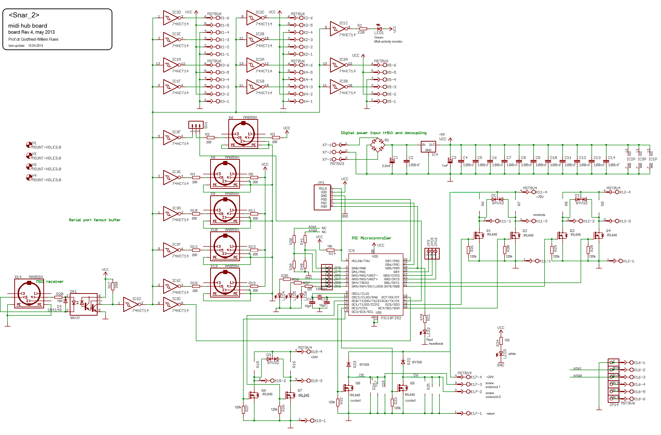
PIC-processor board: MidiPulseHold Rev.2, 2006.
Circuit drawing:
Power supply, circuit drawing:
Solenoid data:
Beaters: Linear tubular solenoids, push type, diameter 20 mm. Two types/brands can be used:
1.- Saia Burgess type 195225-229, STA, 9.4 V dc @ 100% - 7 Watt, nominal traject 5.1 mm, maximum traject 17.8 mm. Length:39 mm, Plunger: 15.3 g. Total weight: 87.3 g. DC-resistance: 12.8 Ohm. Maximum power @ 10% duty cycle: 70 Watt, 11.9 N. Mounting thread: M14 x 1.5.. Lifetime: 25 million cycles. (= 86 days uninterrupted rolls at 8 cycles a second). [This type used for <Snar>].
2.- Black Knight, type 121-420-620-620, 12V dc @ 100%. DC resistance: 20 Ohm. Mounting thread: 18UNF - 0.562" (13,8 mm) [This type used for Snar_2].
Beater-heads: Bakelite balls, with M3 thread, diameter 10mm.
Solenoids used for the snare pulling mechanism: Tremba Gmbh Zylinderhubmagnet ZMF-3864Z.001 24 V DC @ 100% Duty cycle. Conrad order nr. 542-162-17 (Anchors modified with fall through stopper).
Solenoids used for the rimshot sticks: Tremba Gmbh ZMF-3258Z.001 24 V DC @ 100% Duty cycle, pull type. ( On <Snar> we used: Saia Burgess type 195225-229, STA, 9.4 V dc @ 100% - 7 Watt).
Drumsticks: Premier M10, diameter 14 mm. If the drumsticks need replacement, first determine the pivoting point for optimum rimshot sound and drill a 3 mm hole at that point. Then the vertical hole, also 3 mm can be drilled for the solenoids drive mechanism. Finish the replacement by placing the counterweight ring on the drum stick. Secure its position with the M6 inbus setscrew provided.
Drumskins:
- drumhead: Remo
- resonant head: Remo
PIC microcontrollers:
- PIC1: 18F2525-I/SP (steers the two snare solenoids, the two rimshots and the lights inside the drum)
- PIC2: 18F4620-I/SP (steers the 13 beaters inside the drum)
Datasheet for the 18F2525 and 18F4620 processors (PDF file from Microchip)
Wheels: building height 65 mm, with brakes.
 The M3 thread inside the plunger was done by hand. The threaded M3 shaft is
turned into the M3 internal thread in the plunger with Loctite fastener. Both
snare solenoids mounted on the drum using M4 x 10 bolts and two growers as
standoffs.