More than a century ago, the first aviation pioneers figured out a way to use rigid wings with flaps to generate enough force to lift a heavy craft into the sky. It was one of the great advances in human history and also the beginning of a new era in transportation. Airplanes, and the airline industry that depends on them, are now among the world’s largest businesses, with air travel producing over US $700 billion in annual revenues.
However, commercial airlines spend more than 25 percent [pdf] of their operating expenses on fuel, earning the industry a reputation for razor-thin margins that will eke out just $39 billion [pdf] in profits this year. Meanwhile, modern aircraft wings and engines have reached near-peak levels of efficiency, making it exceedingly difficult for engineers to generate additional savings.
And yet, there is one promising strategy that remains—changing the shape of the aircraft wing during flight. For three decades, engineers at aerospace companies, universities, and defense labs have been working on twistable aircraft wings that could be instantaneously and minutely adjusted to improve fuel efficiency. With these wings, aircraft designers could get closer to optimal performance by increasing an airplane’s lift-to-drag ratio, which is a measure of aerodynamic efficiency, in response to variations in speed, altitude, air temperature, and other flight conditions.
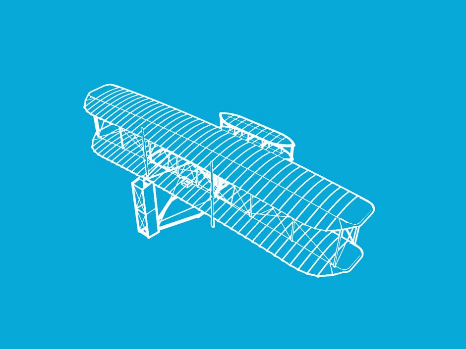
This modern pursuit has a notable historical precedent. Way back in 1905, Orville Wright steered the brothers’ pioneering airplane by lying prone in a saddle and twisting the tips of the plane’s fabric-and-wood wings with a sway of his hips. Soon after, as aircraft became heavier, engineers switched to stiff wings controlled by rigid flaps and ailerons, and morphing these surfaces proved impractical.
Decades later, in the mid-1980s, the U.S. Air Force tested Mission Adaptive Wings that were built by Boeing and installed on an F-111 aircraft. An automated control system reshaped the thin outer covering of these wings to change their curvature, thereby reducing drag by up to 20 percent, for supersonic flight. Unfortunately, the added weight and power demands of this technology made the aircraft less efficient overall. From 1996 to 2005, the U.S. Air Force collaborated with NASA to develop an Active Aeroelastic Wing, which used the power of the airstream to twist itself for better roll control during high-speed maneuvers. But that technology was intended only for fighter jets, and the program eventually lost support.
The flexible wing concept has matured greatly since then. My colleagues and I have built a shape-changing control surface that in recent tests, conducted with the technology installed in place of traditional flaps on the wings of a Gulfstream III jet, reduced drag to a degree that could improve airplanes’ fuel efficiency by up to 12 percent. The flexible surface adjusted the curvature of the wings’ trailing edges to deliver an optimal lift-to-drag ratio throughout the test flights, whereas flaps on today’s airplanes pivot to generate lift or drag only during takeoffs and landings. In addition to saving fuel, analyses by NASA and other researchers have shown that this surface could also lead to quieter landings and possibly even less turbulent flights.
Flexible wings solve an old problem in fixed-wing flight. Airplanes need the right blend of lift and drag to handle changing flight conditions. Generally, a pilot’s goal is to reduce drag in order to preserve fuel. However, an aircraft’s wings are designed to produce minimum drag at only one particular flight condition, which is determined by the aircraft’s anticipated cruising weight, speed, altitude, and range. And the flaps and other control surfaces can be adjusted only in relatively crude increments to improve the lift-to-drag ratio as conditions change.
Unlike traditional wings, though, wings with shape-changing control surfaces can minimize drag for a wide range of conditions—a feat that has never before been achieved in commercial flight. Our most advanced version of the technology will be integrated into existing flaps along the wings’ trailing edges on retrofits or installed in place of flaps on new planes. If all goes well, we will be able to test it on a commercial airliner within the next three years.
The initial flash of inspiration for my flexible wing struck me as I was driving on a rainy day in Michigan in the early 1990s. As the windshield wipers swished back and forth, I realized their shape did not fit the face of the glass. It occurred to me that even when designing a wiper for a curved windshield, engineers still use straight, rigid parts connected by joints prone to wear and tear.
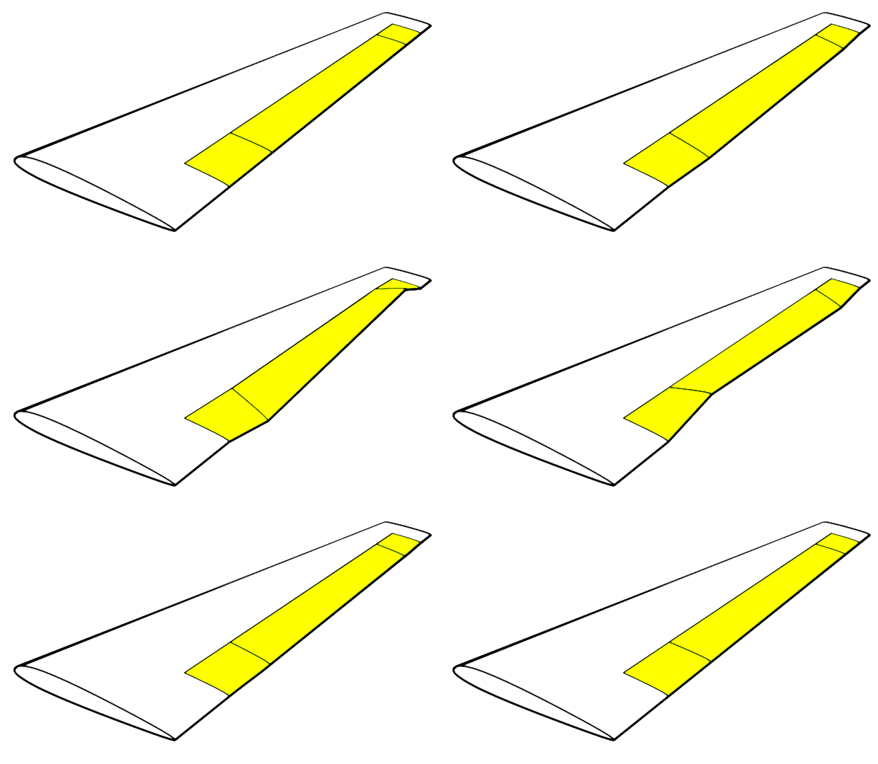

I began to think about objects whose performance might benefit from their ability to change form. I had once taken a design course on aircraft wings and knew that, when designing a new plane, aerospace engineers assume a wing’s shape will not change during flight. But it seemed to me that a hingeless, gapless, shape-changing wing could improve fuel efficiency for many more flight conditions.
The traditional aircraft wing is a relatively rigid structure with various movable control surfaces: flaps, ailerons, and spoilers. Flaps, which are panels on the trailing edge of the wing, are used during takeoffs and landings to generate lift at low speeds. Ailerons are segments on the trailing edge near the wing tips. Operated in pairs, one on each wing, they cause one wing to go up and the other to go down, to make the aircraft roll into a turn. Spoilers are panels on the top of the wing that, when rotated upward, increase drag and quicken a plane’s rate of descent.
Although these control surfaces work quite well, they can only pivot rather than morph their shape. And flaps are typically not deployed during flight because their joints and hinges are full of gaps, which would cause too much drag. Though some new airliners allow pilots to make minute adjustments to ailerons and flaps to reduce drag while cruising, pilots still can’t truly tailor the aerodynamic performance of traditional wings in response to warmer temperatures, higher altitudes, or stronger wind speeds. The result is not unlike riding to the top of a hill on a bicycle in the wrong gear—you may get there, but with considerably more effort than if you’d switched to a lower gear.
A plane could switch gears, so to speak, and achieve a more optimal lift-to-drag ratio by changing the shape of its wings. To understand how this would help, first consider how wings generate lift. A standard airplane wing is more curved on top than on the bottom, so that it diverts masses of air downward, providing lift. The curved top surface of the wing is mainly responsible for pushing the air downward, so, to some extent, enhancing the camber (or curvature) of this surface can improve a plane’s lift-to-drag ratio.
For any airplane’s combination of weight, altitude, and speed, there is an ideal wing camber that delivers the required lift and also achieves the lowest drag. Much of the aerodynamic research to figure out which camber adjustments would deliver the best performance under specific conditions has already been done. But the experts who carried out that theoretical work have had no means of implementing it on an actual plane until now.
Unlike wings with flaps, a flexible wing can smoothly adjust its camber to minimize drag during flight. In fact, a flexible wing could assume many more positions than a wing with a traditional flap, allowing for much finer control over the lift-to-drag ratio to match the evolving demands of a flight. And if the flexible control surface fits smoothly against the rest of the wing, these adjustments would create no additional drag from protruding joints and hinges.
The upshot is that altering the wings’ camber during flight allows aircraft designers to minimize drag depending on how much lift a plane needs for specific conditions. For example, the burning of fuel during flight diminishes the overall fuel weight, so the plane gradually requires less lift. Currently, pilots contend with this weight loss by reducing the aircraft’s angle of attack, which is its angle relative to the oncoming flow of air. A flexible wing could simply morph the surface of its trailing edge continually throughout an entire flight to achieve the optimal camber for its current fuel weight.
The ability to fly well in a variety of flight conditions is important because aviation rules limit the speeds and altitudes at which airplanes can travel. In the United States, the Federal Aviation Administration, for example, reserves odd-numbered altitudes (such as 31,000 feet) for flights traveling north and east while south- and westbound flights stick to even-numbered levels. Invariably, planes wind up cruising at a combination of speed and altitude that is not aerodynamically optimal. But a flexible wing could be tailored to fly more efficiently at any assigned altitude or speed.
Aside from reducing drag, there is another potential benefit of shape-changing wings that passengers especially will appreciate. These wings can also dampen the shaking of the fuselage due to turbulence. This can be achieved by twisting the wings’ trailing edges in just the right way so as to reduce the loads caused by turbulence and thus minimize the movement transmitted to the fuselage. This twisting would be done automatically by a sophisticated flight control system.
When I began to sketch the original diagrams for my flexible wing in my home office, in 1994, I had no background in aerospace engineering. I was also oblivious to the many failed attempts to design a shape-changing wing that preceded my own. I later learned that those earlier designs were complex affairs incorporating hundreds of parts and dozens of motors.
From the start, I resolved to make my design strong but flexible, with no joints or hinges, and to forge it from a single piece of material. Powered by one or two electric motors, it would perform all the necessary functions for flight while enduring the massive aerodynamic pressures created by heavy aircraft flying at high speeds.
At this point, I was still working from home in my free time and without a cent of external funding. Not long after I had completed the first batch of sketches, though, I read a magazine article about the U.S. military’s latest attempts to develop a shape-changing airplane wing at Wright-Patterson Air Force Base in Dayton, Ohio. I visited the base and showed the research team my designs. Then in 1998, Wright-Patterson’s Air Force Research Laboratory awarded me a $100,000 contract to develop a feasibility analysis for flexible wings. I didn’t know it at the time, but that funding was the first of more than $50 million the U.S. government would spend over the next 18 years to test my concept in various wind tunnels, and in flight.
To start, I spent the first check from Wright-Patterson to design and rapidly prototype (using what is now called 3D printing) a plastic model of my wing and rent a wind tunnel at the University of Michigan, where I am a professor of mechanical engineering, to conduct a few basic tests. My design performed well in the wind tunnel and appeared scalable, so in 2001 the Air Force awarded me another contract and more money to build a larger prototype that could be tested at higher wind speeds.
It was about this time that I founded FlexSys in Ann Arbor, Mich., and dubbed my wing FlexFoil. After several more successful tests with the larger prototype, my Air Force collaborators said they were ready to test our design on an actual flight of a White Knight aircraft, which is the same plane that carried the pioneering private space vehicle SpaceShipOne.
For these tests, as a safety precaution, we hung a 127-centimeter aluminum version of the FlexFoil control surface vertically from the underside of the aircraft rather than attaching it directly to the plane’s wings. During flight, we manipulated the camber and shape of FlexFoil remotely from the cabin and monitored performance through pressure ports and thermal sensors that we had installed on the suspended prototype to measure lift and drag.
The White Knight flew multiple tests for us in the Mojave Desert in the summer of 2006. In all of them, FlexFoil demonstrated a significant reduction in drag while enduring the stresses and temperature fluctuations of flight. We also showed that at every stage of flight from takeoff to landing, FlexFoil could reduce drag for a given amount of lift. Another analysis by NASA showed that the technology could improve lift over drag by up to 10 percent.
The best news, though, was that measurements collected during those flights suggested that FlexFoil would boost fuel efficiency by 8 to 12 percent if installed in place of flaps on new airplanes, and by about 3 percent for retrofits, in which the technology would be integrated into the existing flaps along the wings’ trailing edges. For comparison, the new winglets that have recently been installed on many planes cost at least $1 million per pair and deliver fuel savings of 4 to 5 percent.
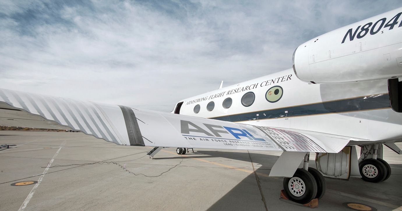
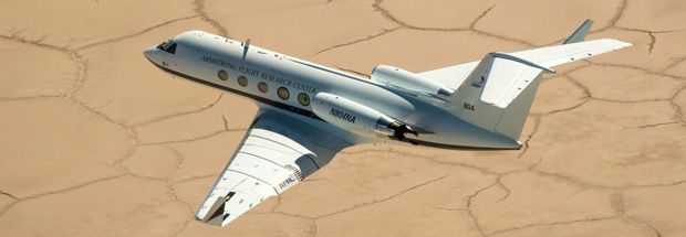
Encouraged by this success, in 2009, the Air Force Research Lab at Wright-Patterson and NASA asked us to retrofit a Gulfstream III aircraft. This time, the mission would be to test FlexFoil on the wings of the airplane rather than dangling it from below, as we did during the White Knight flights.
For this round, we made a new prototype and replaced each of the jet’s flaps with a 7-meter span of FlexFoil that ran along the length of the wings’ trailing edges. This installation is similar to what we would do for an installation on a brand new airplane.
This prototype was made from common aerospace-grade materials such as aluminum alloys and composites. We built it with design tools and algorithms produced by my team that allowed us to arrange curved and straight structural beams into a pattern so that each beam bent like a bow in response to force. This pattern formed the internal skeleton of a FlexFoil span. Placing pressure at one or two points on the structure changed the entire span’s shape depending on how much force was applied and where it was placed.
The finished control surface weighed approximately 110 kilograms (about 240 pounds), which was roughly the same as the flaps and associated guide tracks that it replaced. At each end of the span, elastic mechanisms covered in an elastomer skin formed an accordion-like bridge to the wing that expanded and contracted as FlexFoil morphed, with no external joints or hinges to hinder the flow of air.
NASA’s acoustic experts have estimated that this seamless covering [pdf] would allow FlexFoil to potentially reduce a plane’s landing noise [pdf] by 40 percent. The agency was scheduled to conduct flight tests to verify such benefits beginning this month. Airframe noise, which is much louder than engine noise during landings, is caused by air flowing through the gaps between traditional flaps and wings.
In a conventional airplane wing, the flaps are moved by a pair of hydraulic cylinders. For simplicity, our prototype was designed to connect to those cylinders as well. As I envision the commercial version, a flight control system could change the camber of FlexFoil using only one motor per wing, while twisting its shape would require two (one to pull, and one to push). Because these motors already exist in a typical large aircraft wing, the design would not be subject to the additional testing that regulators would require if I were to bring a new power source on board.
After the Air Force invited us to outfit the Gulfstream III, it took five years to complete the design, installation, ground testing, and scheduling required for the first flight. FlexFoil and the aircraft were again fully instrumented by NASA to record flight conditions and measure how well the technology endured high wind speeds, low temperatures, and sudden changes in air pressure. FlexFoil alone had 112 strain gauges, 60 accelerometers, and enough sensors to gather over 4,300 data points during each flight.
On 6 November 2014, the Gulfstream III took to the skies of the California high desert, held aloft by the world’s first modern pair of flexible wings. For safety during these initial tests, we did not change the wings’ shape throughout flight, but rather manipulated FlexFoil on the ground. Over a series of 22 flights above NASA’s Armstrong Flight Research Center in Edwards, Calif., those wings took on shapes that varied their camber from 2 degrees up to 32 degrees down. In other words, the wings’ trailing edges raised slightly and then rotated down to about the same position used by traditional flaps for takeoff.
Afterward, our data showed that FlexFoil produced a maximum of 5,000 kilograms of lift while it was set into these positions. It achieved this lift while the aircraft executed a range of maneuvers at altitudes of 20,000 to 40,000 feet under heavy loads. During the tests, the aircraft was subjected to a maximum dynamic pressure of 1,875 kilograms per square meter, which is well above the load that any commercial aircraft would ever experience. In every case, FlexFoil performed flawlessly.
Based on data from the tests, FlexFoil was able to withstand temperatures ranging from –53 °C to 82 °C and estimated to last five times the life cycle of a commercial aircraft. The results showed for the first time that practical, lightweight, and durable shape-changing surfaces installed on modern aircraft can deliver top performance under a wide range of flight conditions.
Our priority now is to make aviation leaders, who are understandably cautious when it comes to radically new technologies, aware of the advantages and reliability of our shape-changing wing. Last November, we entered into a joint venture with Seattle’s Aviation Partners, which sells efficiency-boosting winglets for airliners. Together, we created a new company called Aviation Partners FlexSys to commercialize FlexFoil. We plan to test it on a commercial aircraft by 2020.
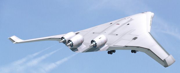
The technology also fits very well with a coming generation of aircraft that, aviation experts predict, will blend wings and fuselage together in one seamless design. In particular, Boeing and NASA have experimented with a futuristic blended-wing aircraft, which FlexFoil could transform into a fantastically smooth, quiet, and efficient flier.
In the more distant future, our flexible control surface could find applications beyond fixed-wing flight. Any object moving through air, or water, could benefit. My colleagues and I have already developed prototypes of helicopter rotor blades that would morph their leading and trailing edges several times per revolution to improve performance. Early demonstrations show that these blades can change shape up to 15 times per second, which could improve a helicopter’s lift-to-drag ratio and reduce vibration. Other applications might include components for submarines, automobiles, and wind turbines.
It’s not unusual for it to take at least 15 years to develop and test a new technology for commercial flight, but the turnaround time for these other applications could be much faster if engineers embrace flexible design as a principle that can deliver more efficient shape-changing forms, as I have found to be true for flight.
This article appears in the September 2016 print issue as “Twistable Wings Take Flight.”
Sridhar Kota is a mechanical engineering professor at the University of Michigan and CEO of FlexSys based in Ann Arbor, Mich. He focuses on bio-inspired designs and pioneered the concept of distributed compliance for flexible design. He has also served in an advisory role focused on advanced manufacturing for the White House Office of Science and Technology and Policy.
