Author: persmule Mail: persmule@tya.email, persmule@gmail.com
00 ME: Management Engine
First introduced in Intel’s 965 Express Chipset Family, the Intel Management Engine (ME) is a separate computing environment physically located in the (G)MCH chip (for Core 2 family CPUs which is separate from the northbridge), or PCH chip replacing ICH(for Core i3/i5/i7 which is integrated with northbridge).
The ME consists of an individual processor core, code and data caches, a timer, and a secure internal bus to which additional devices are connected, including a cryptography engine, internal ROM and RAM, memory controllers, and a direct memory access (DMA) engine to access the host operating system’s memory as well as to reserve a region of protected external memory to supplement the ME’s limited internal RAM. The ME also has network access with its own MAC address through the Intel Gigabit Ethernet Controller integrated in the southbridge (ICH or PCH).
The Intel Management Engine with its proprietary firmware has complete access to and control over the PC: it can power on or shut down the PC, read all open files, examine all running applications, track all keys pressed and mouse movements, and even capture or display images on the screen. And it has a network interface that is demonstrably insecure, which can allow an attacker on the network to inject rootkits that completely compromise the PC and can report to the attacker all activities performed on the PC. It is a threat to freedom, security, and privacy that can’t be ignored.
01 Early efforts to remove ME
The ME’s boot program, stored on the internal ROM, loads a firmware “manifest” from the PC’s SPI flash chip. This manifest is signed with a strong cryptographic key, which differs between versions of the ME firmware. If the manifest isn’t signed by a specific Intel key, the boot ROM won’t load and execute the firmware and the ME processor core will be halted.
The ME working with Core 2 processors (Q43, Q45, GM45 and the like) can be disabled by setting a couple of values in the SPI flash memory. The ME firmware can then be removed entirely from the flash memory space. librebootdoes this on the Intel 4 Series systems (GM45, GS45, G41, etc) that it supports, such as the Libreboot X200 and Libreboot T400. Later ME found on all systems with an Intel Core i3/i5/i7 CPU and a PCH, include “ME Ignition” firmware that performs some hardware initialization and power management. If the ME’s boot ROM does not find in the SPI flash memory an ME firmware manifest with a valid Intel signature, the whole PC will shut down after 30 minutes.
(The above two paragraphs are excerpted from this article, with some minor modifications)
02 Minimize ME’s power on platforms with PCH
As mentioned above, completely removing the ME is hardly possible on platforms with PCH, so (at least) my goal on such platforms should be:
Leave minimalist ME function to keep the whole system stable (thus prevent the 30-minute-shutdown Defective by Design), and then remove all remaining function unrelated to this, especially those threatening our freedom, security, and privacy.
ME’s sectional and modular design makes it possible. Different ME modules are stored in different partitions in the ME region of the SPI flash, and their signature are verified separately, so it is possible to completely prevent one module being loaded without interfering another.
On sep. 2016, Trammell Hudson detected that erasing the first 4kiB page of the ME region did not shutdown his x230 30 minutes later.
Finally on Nov. 2016, Nicola Corna and Federico Amedeo Izzo found that Sandy Bridge accepts an Intel ME firmware with just the FTPR partition (containing the kernel of the RTOS of ME), both with and without a valid FPT (the partition table of the Intel ME image), and they wrote a python script that removes all the non-fundamental partitions and creates a new FPT with a single FPTR partition entry, and few days later they published the script on github.com.
With that script and coreboot’s utilities, I successfully neutralized the ME firmware on my x220, with vendor bios untouched.
The boot firmware (BIOS and the like) on a platform with ME consists of a firmware descriptor containing every region’s offset, size and access permission, and several regions containing various codes and data.
Below is a descripter of a boot firmware, printed by flashrom(8):
=== Region Section ===
FLREG0   0x00000000
FLREG1   0x03ff0260
FLREG2   0x025f000b
FLREG3   0x00020001
FLREG4   0x000a0003

--- Details ---
Region 0 (Descr.) 0x00000000 - 0x00000fff
Region 1 (BIOS  ) 0x00260000 - 0x003fffff
Region 2 (ME    ) 0x0000b000 - 0x0025ffff
Region 3 (GbE   ) 0x00001000 - 0x00002fff
Region 4 (Platf.) 0x00003000 - 0x0000afff

=== Master Section ===
FLMSTR1  0x1a1b0000
FLMSTR2  0x0c0d0000
FLMSTR3  0x08080218

--- Details ---
      Descr. BIOS ME GbE Platf.
BIOS    r     rw      rw   rw
ME      r         rw  rw
GbE                   rw
flashrom(8), a flash programming tool whose project cooperates with coreboot, is able to operate the on-board SPI flash containing the boot firmware via its internal driver. Unfortunately, on most platforms with ME, like the example above, the ME region is usually readable only for ME hardware, not the main CPU, which prevents us from using flashrom(8) with internal programmer to even read the whole content of the vendor firmware. In order to research the boot firmware, we need an external programmer.
There are a lot of external programmers usable to flashrom(8) available in China, from cheap ch341a_spi, to more professional buspirate_spi. According to my experience, those dedicated external programmers are feasible to program solitary SPI flash chips, but not feasible for in-system programming, because their electrical current to program chips may be too small, as other components on circuit may disperse the current, and dispersed current is not enough to program, even detect the chip.
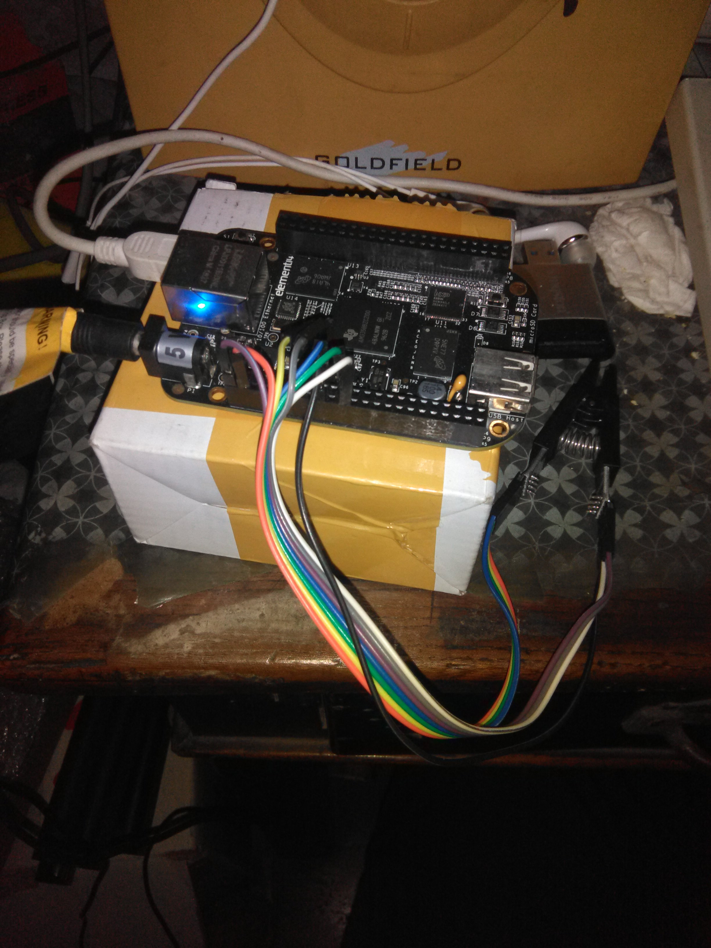
Fortunately, the SPI bus available on some ARM development boards is usually powerful enough, so I use a BeagleBone Black (BBB) rev.c as my external in-system programmer:

I have configured my BBB according to this guide, using a statically built ARM architecture flashrom(8) executable file provided by libreboot (here, put under /opt/flashrom/) to power its SPI bus with linux_spi driver.
04 Read the content of the SPI flash chip via In-System Programming.
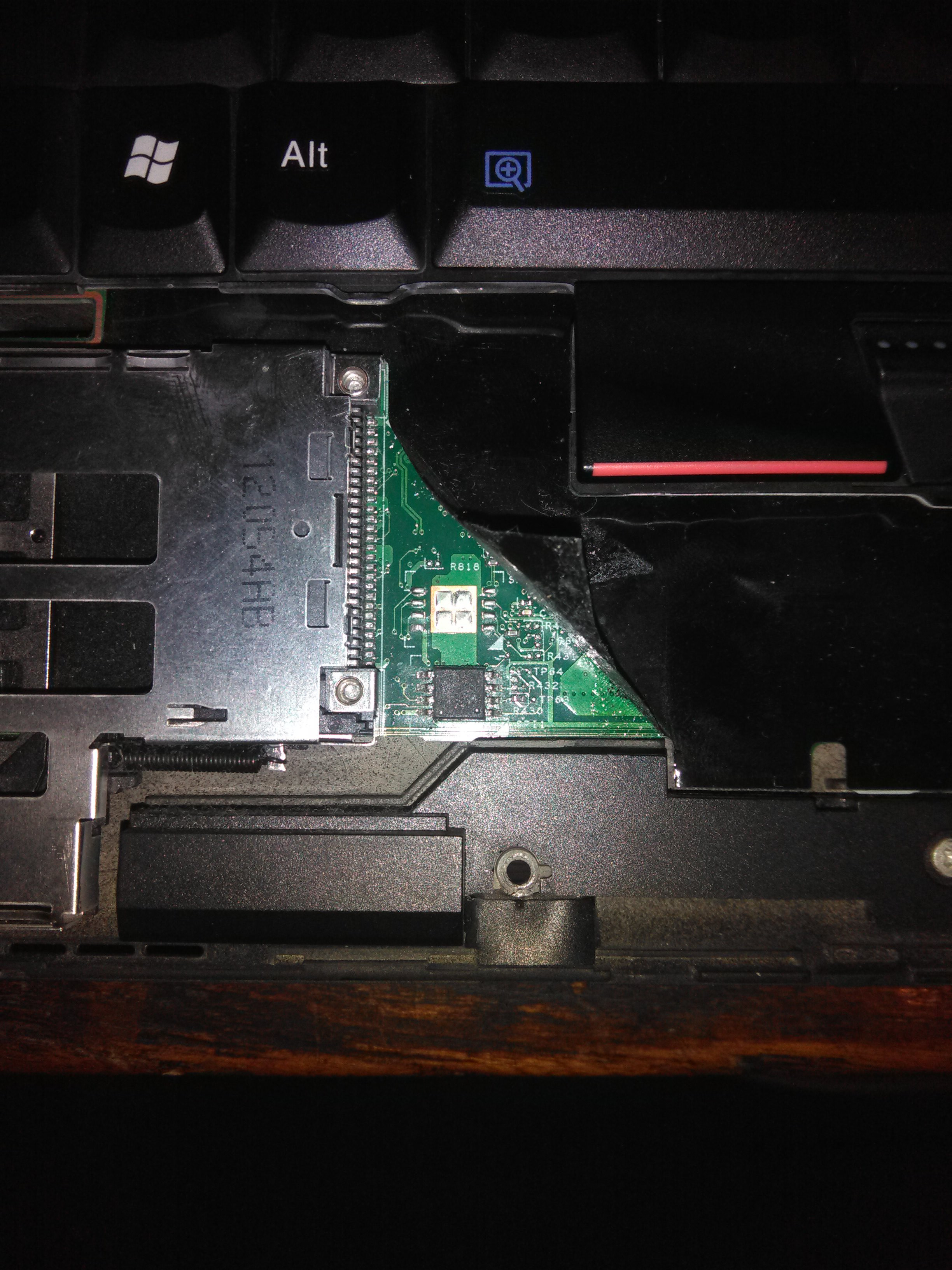
Remove all power supply (AC and battery) of Thinkpad x220, then remove its keyboard and palmrest, according to its maintenance manual, to expose its 64Mibit (8MiByte) SOIC-8 SPI flash chip.

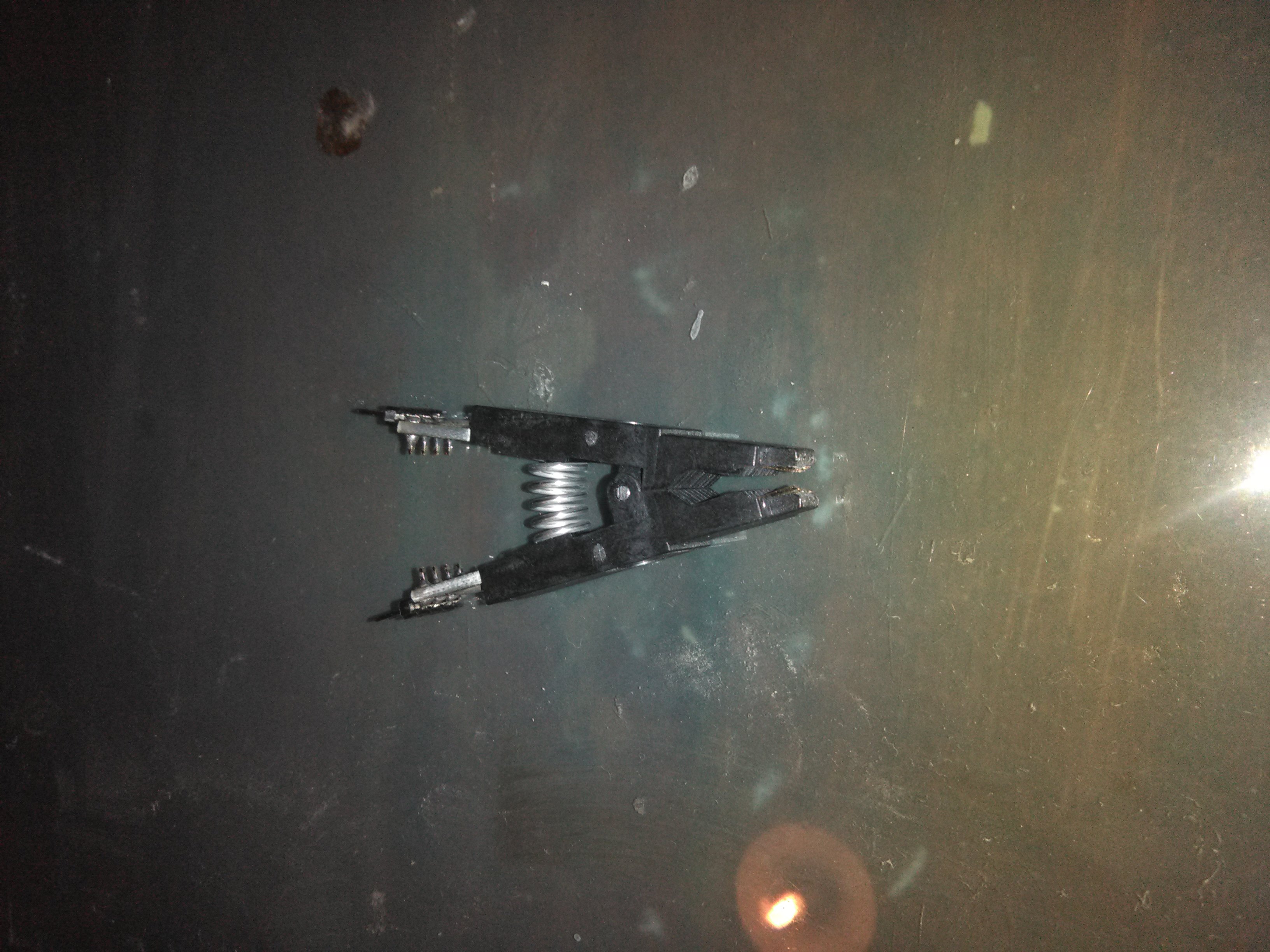
So I am going to use the configuration below to connect the chip to BBB, with a cheap SOIC-8 clip available in China which I have used to program other boards.

===  front (display) on your X220 ====
 18              -       - 1
 22              -       - NC
 NC              -       - 21
 3  [3.3V (PSU)] -       - 17 - this is pin 1 on the flash chip.
===  back (palmrest) on your X220 ===
Unfortunately, the tip of the clip is worn out, insufficient to grab the chip, but fortunately I still have a SOIC-16 clip with uneven pins to program libreboot to x200, half of whose tip is just sufficient to grab the SOIC-8 chip. Its uneven pins also have enough space for dupont wires to connect.

With an additional 5V power supplier connected, the BBB has enough voltage and current to perform in-system programming, and I connect BBB to my desktop PC via its mini type B USB peripheral port, via which I could get usbnet access:
$ ssh -C root@beaglebone.localConnect the clip to the chip, with 3.3v power disconnected, and then connect the power wire to BBB in order to power the chip, otherwise BBB’s OS is very likely to crash.

Now, try to identify the chip(if detection failed, try to slow down the speed).
root@beaglebone:/dev/shm# /opt/flashrom/flashrom -p linux_spi:dev=/dev/spidev1.0,spispeed=4096And read the content of the SPI flash if the chip is successfully identified. If flashrom(8) feels ambiguity, specify one of its suggested chip model with -c.
root@beaglebone:/dev/shm# /opt/flashrom/flashrom -p linux_spi:dev=/dev/spidev1.0,spispeed=4096 [-c <model>] -r factory_x220.bin
root@beaglebone:/dev/shm# /opt/flashrom/flashrom -p linux_spi:dev=/dev/spidev1.0,spispeed=4096 [-c <model>] -r factory_x220.bin.1
Read chip at least twice, and make sure that all the resulted images are the same (e.g. by checksum), otherwise they cannot be considered reliable.
The rom image factory_x220.bin should be 8MiB large. Copy it to the PC with scp(1).
05 Anatomize the vendor BIOS image.
Coreboot provides ifdtool to analyze firmware images with firmware descripter. Its source code is located in $COREBOOT_SRC/util/ifdtool, it should be make(1) first.
Then ifdtool could be used to dissect the vendor BIOS image:
$ path/to/ifdtool -x factory_x220.binAfter the execution, every region is separated to an individual file.
06 Neutralize the ME.
Finally, the despicable ME firmware is on the chopping board. Use Nicola Corna’s me_cleaner to neutralize it.
$ python3 /path/to/me_cleaner.py intel_me.binNote that me_cleaner will modify the ME file in place, so make a copy for it to modify is recommended.
Then insert the neutralized ME back to the firmware image, still using ifdtool.
$ path/to/ifdtool -i ME:intel_me.bin factory_x220.binUnlike me_cleaner, ifdtool is designed not to modify input file, but generates a new file suffixed with .new instead.
(In reality, I have not only neutralized the ME, but unlocked write access to all region for main CPU with $ path/to/ifdtool -u factory_x220_meneuted.bin, hoping to ease the programming of coreboot later, but after the modified image written back, lenovo’s BIOS still locks the SPI flash, making flashrom(8) in the OS unable to write (but able to read) the flash.)
07 Write the modified image back.
Copy the modified firmware image back to BBB.
$ scp -C factory_x220.bin.new root@beaglebone.local:/dev/shmThen connect BBB to the SPI flash like procedure 04, invoke flashrom(8) to write the image back.
root@beaglebone:/dev/shm# /opt/flashrom/flashrom -VVp linux_spi:dev=/dev/spidev1.0,spispeed=4096 [-c <model>] -w factory_x220.bin.newThe writing procedure is presented with increased verbosity: flashrom(8) will read the old content of the chip first, then compare every 4KiB page between the old content and the provided image file, and only write different pages, either by rewriting (EW), by modifying (W) if only (1->0) occurred, or by erasing (E) if target page should only consist of all 1 (FF). Finally, flashrom(8) verifies the content just written with the provided image file.
08 Results.
With ME neutralized, the MEI interface disappears from the PCI bus, and the integrated NIC ceases to work, but will resume to work after a reboot. All other components work just fine, with no 30-minute-shutdown.
According to Nicola Corna, the current ME state should have been changed from “normal” to “recovery”.
09 Future.
According to Trammell Hudson, the content of FTPR partition of ME could be further cleansed, while me_cleaner leaves an unmodified FTPR.
10 Readings.
Igor Skochinsky’s slide about ME